Knowledge of photovoltaic systems
A photovoltaic system is mainly composed of photovoltaic modules, combiner boxes, power distribution cabinets, inverters, transformers and other equipment.
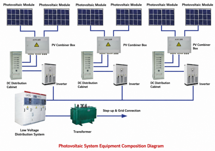
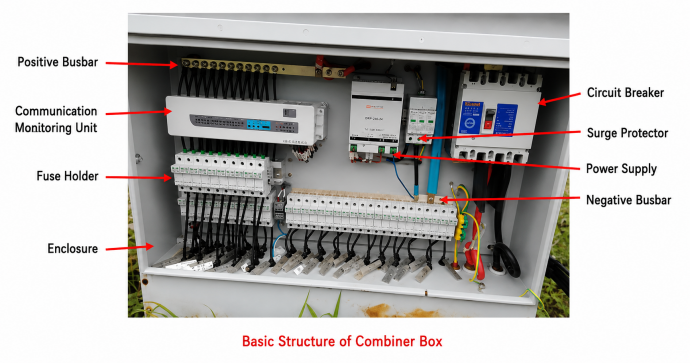
Function of combiner box: It connects multiple photovoltaic strings in parallel for current convergence, with monitoring and protection functions. It reduces wiring between photovoltaic modules and inverters, facilitates maintenance and improves system reliability.
2. Power Distribution Cabinet
Function: It realizes secondary current convergence and provides protection for upper and lower-level circuits in practical application.
3. Inverter
Function: The direct current generated by the photovoltaic array is converted into sine-wave alternating current by the inverter, which is then fed into the power grid.
4. Transformer
Function: Transformers are used for voltage step-up and step-down. Stepping up voltage can effectively reduce power transmission loss.
5. Photovoltaic Module
5.1 Definition
Solar cells are the basic units of photovoltaic modules. Single solar cells cannot be used as power sources directly, so a number of them need to be connected in series and parallel and tightly encapsulated to form modules.
Also known as solar panels, photovoltaic modules are core components of photovoltaic power generation systems. They convert solar energy into electric energy to drive loads.
5.2 Classification
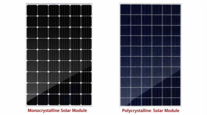
Commonly used modules in photovoltaic power stations include monocrystalline silicon modules, polycrystalline silicon modules and thin-film photovoltaic modules.
Visually, monocrystalline silicon modules are dark blue nearly black with rounded corners on cell pieces. Polycrystalline silicon modules are sky-blue with square cell pieces featuring ice-flower-like textures on the surface.
Thin-film photovoltaic modules mainly include perovskite, Cadmium Telluride (CdTe), Copper Indium Gallium Selenide (CIGS) and Gallium Arsenide (GaAs). Amorphous silicon cells fall into the category of thin-film cells. In addition, the popular Heterojunction (HIT/HJT) technology deposits amorphous silicon thin films on crystalline silicon, which is a combination of monocrystalline silicon cells and amorphous silicon cells.
In terms of service performance, the photoelectric conversion efficiency of monocrystalline silicon photovoltaic modules is around 21%, with a maximum of 24%, yet they come with high production costs. Encapsulated with tempered glass and waterproof resin, they are sturdy and durable, boasting a service life of 15 years on average and up to 25 years at most.
Polycrystalline silicon photovoltaic modules have a much lower photoelectric conversion efficiency of approximately 17%, but feature lower manufacturing costs, hence achieving widespread application. Nevertheless, their service life is shorter than that of monocrystalline silicon panels, making monocrystalline silicon slightly superior in cost performance.
Heterojunction cells integrate the strengths of crystalline silicon cells and thin-film cells. Compared with other photovoltaic cells, they deliver higher conversion efficiency and better stability. Their main drawback lies in high costs, including huge equipment investment and large consumption of silver paste, resulting in relatively poor cost performance at present.
As a representative of third-generation non-silicon thin-film cells, perovskite boasts the following advantages:
(1) Low material consumption. Thanks to its strong light absorption capacity, it requires extremely little raw material. The thickness of the perovskite layer in modules is about 0.4μm, while the wafer thickness of crystalline silicon modules is generally 180μm, a difference of 450 times.
(2) Low manufacturing process requirements, simple production procedures, shortened industrial chain and low cost.
Crystalline silicon materials must reach a purity of over 99.9999% (six nines) for solar cell production, whereas perovskite materials only need around 98% purity to fabricate solar cells with efficiency above 20%.
Monocrystalline silicon production requires melting silicon raw materials at temperatures above 900℃, while the processing temperature of all functional layers of perovskite is below 180℃, and most procedures require no vacuum environment.
In addition, crystalline silicon products including silicon raw materials, silicon wafers, cells and modules need to be manufactured in more than four separate factories, and it takes about three days to finish one module. In contrast, perovskite modules can be fully produced in a single factory. The whole process from feeding glass, adhesive films, target materials and chemical raw materials to finished modules only takes 45 minutes.
(3) High photoelectric conversion efficiency. After photons absorbed by perovskite are converted into electrons, its carriers feature a long diffusion length of several micrometers, far exceeding the thickness of perovskite thin films. Electrons can be easily collected by electrodes with low energy loss, thus generating high photovoltage and photocurrent and achieving excellent overall conversion efficiency.
The theoretical maximum conversion efficiency of single-junction perovskite cells reaches 31%, and that of multi-junction cells exceeds 50%, far higher than that of crystalline silicon cells.
(4) Excellent low-light performance. Perovskite photovoltaic cells maintain high photoelectric conversion efficiency under weak light conditions. In the future, they can generate power by utilizing weak indoor ambient light and dim sunlight on cloudy days, which is a major advantage over traditional silicon-based photovoltaics.
Nevertheless, perovskite cells also have disadvantages:
(1) Limited size. High-efficiency perovskite cells are only available in laboratory specifications and have not achieved commercial large-size production.
(2) Poor stability. Oxygen oxidation, light irradiation and ultraviolet rays will seriously impair the stability of perovskite cells.
(3) Relatively short service life. At present, the maximum service life of perovskite cells is only 3000 hours (125 days), while crystalline silicon cells can last up to 25 years.
(4) Toxic raw materials. Perovskite cells contain lead, which is toxic and may cause environmental pollution.
(5) Immature coating technology. It is difficult to coat perovskite layers evenly on equipment surfaces, which greatly undermines device performance. Advanced spraying technologies are urgently needed for improvement.
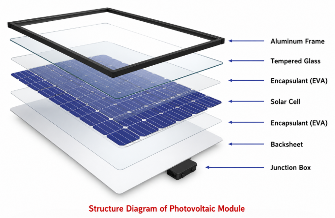
5.3 Structure of Photovoltaic Modules
Photovoltaic modules are made by connecting solar cells in series and parallel, then hot-press sealing with tempered glass, encapsulant film and backsheet. Aluminum alloy frames are installed around the edges. They feature strong wind and hail resistance and easy installation.
(1) Solar Cell: A device that converts light energy into electrical energy via the photovoltaic effect. Its power generation principle is shown in the figure below. When semiconductor-based solar cells absorb sunlight, electrons (negative charges) and holes (positive charges) are generated in P-type and N-type semiconductors. The separation of electrons and holes creates a voltage drop, and electric power is then transmitted to loads through wires.
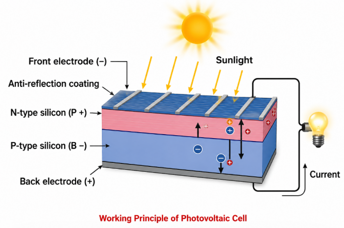
Different wavelengths also affect the conversion efficiency of solar panels. The light absorption band of monocrystalline and polycrystalline silicon solar cells is generally 1100-1200nm, while that of thin-film cells is mostly 800nm, with some reaching 900nm. LED wavelengths range from 460 to 636nm, which cannot support power generation of photovoltaic cells.
(2) Interconnector Ribbon
It is used to connect solar cells in series. One interconnector is welded on the back of each cell to join multiple cells into cell strings.
(3) Busbar Ribbon
It serves as a connector for cell strings, linking assembled cell strings together, and leading out positive and negative poles to connect with junction boxes. Both interconnectors and busbars are tinned copper strips.
(4) Tempered Glass
It is divided into coated glass and ordinary glass. Low-iron ultra-white textured tempered glass is widely adopted, with a light transmittance of over 90% and excellent resistance to solar ultraviolet radiation.
Ultra-white means low iron content; it appears white from the side while ordinary glass looks green. The textured surface is designed to reduce light reflection via anti-reflection treatments such as sol-gel nanotechnology and coating technology. Tempering is achieved by rapid air cooling of molten glass to form surface compressive stress and internal tensile stress, enhancing structural strength.
(5) EVA Encapsulant Film
It is a thermosetting film featuring superior adhesion, durability and optical properties, widely used in photovoltaic modules and optical products. It remains non-sticky at room temperature for easy operation.
Thermosetting materials cannot be softened, reshaped or dissolved in solvents after curing. They soften and flow upon initial heating, then undergo cross-linking reaction to harden irreversibly once reaching a certain temperature. Such materials can be shaped under pressure during the first heating process and solidify into fixed forms, known as thermosetting plastics.
(6) Backsheet
TPT (Polyvinyl Fluoride Composite Film) is the most commonly used backsheet material, which boasts outstanding environmental corrosion resistance, good insulation performance and strong adhesion to EVA film.
(7) Aluminum Alloy Frame
It protects glass edges, improves module sealing performance together with silica gel, enhances overall mechanical strength, and facilitates installation and transportation.
(8) Silica Gel
Functions for bonding and sealing.
(9) Junction Box
An electrical box connecting the positive and negative outgoing wires of photovoltaic modules to external circuits.
Main Factors Affecting Power Generation of Photovoltaic Modules
(1) Inherent Losses from Module Structure
Power loss occurs during cell encapsulation. Part of the loss comes from reduced light incidence and absorption caused by glass, EVA and other materials; the rest is electrical connection loss mainly generated by welding strips and other connecting parts. Natural attenuation also happens during module operation.
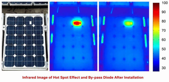
(2) Hot Spot Effect
Shaded solar cells in series branches will act as loads and consume electric energy generated by illuminated cells, resulting in abnormal heat accumulation, which is defined as the hot spot effect.
Hot spots not only lower power generation efficiency, but also cause permanent damage to modules and bring fire hazards to power stations. Statistics show that severe hot spot effect can cut the actual service life of solar modules by at least 30%, and even lead to module failure in the long run. Simple stains, bird droppings, fallen leaves or weeds may trigger this effect.
Junction boxes equipped with bypass diodes are generally installed in modules to mitigate hot spot impacts. Once hot spots occur, the diodes will activate to bypass the faulty cell strings.
Core Professional Terms
PID Effect
Potential Induced Degradation (PID) occurs when photovoltaic modules operate under long-term high voltage. Leakage current forms between glass and encapsulation materials, leading to massive charge accumulation on cell surfaces. This may cause module power attenuation of over 50%, further undermining the power output of the entire string. PID is most likely to occur in coastal areas with high temperature, high humidity and high salinity-alkalinity.
(4) Solar Cell Micro-cracks
Micro-cracks are inherent defects of solar cells. Due to crystal structural characteristics, crystalline silicon cells are prone to cracking. Different cracks exert varying impacts on cell performance. Micro-cracks parallel to busbars cause the most severe damage.
Current generated by cells is collected and conducted out via surface busbars and vertical fine fingers. Once micro-cracks break fine fingers, collected current cannot be transmitted to busbars, resulting in partial or even complete cell failure.
Studies show that 50% of failed cells are caused by busbar-parallel micro-cracks. The power loss caused by 45° inclined cracks is only one quarter of that from parallel cracks. Cracks perpendicular to busbars barely damage fine fingers and hardly lead to cell failure.
Unlike crystalline silicon cells with grid lines, thin-film cells are fully covered with transparent conductive films, which is why thin-film modules are free from micro-crack issues.
(5) Sunlight Irradiation Intensity and Temperature Variation
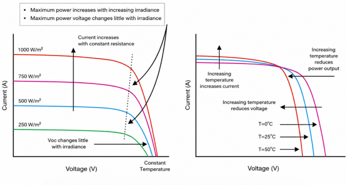
Sunlight irradiance is directly proportional to the photocurrent of photovoltaic cells. When the irradiance varies within 1000-2100W/m², the photocurrent rises linearly along with the increase of irradiance. By contrast, irradiance has little influence on voltage. At a fixed temperature, the open-circuit voltage of photovoltaic modules remains basically stable when irradiance changes from 1000 to 2400W/m². Therefore, the output power of photovoltaic cells is roughly proportional to sunlight irradiance.
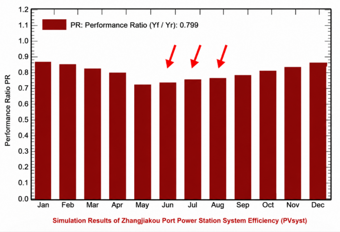
The higher the temperature of photovoltaic modules, the lower their working efficiency. As module temperature rises, output voltage drops. Within the range of 20℃ to 100℃, the output voltage of each solar cell decreases by approximately 5 millivolts for every 1℃ temperature increase, while the output current rises slightly. Overall, the output power declines with rising temperature, dropping by 0.35% per 1℃ increase.
Accordingly, output power fluctuates with seasonal temperature changes. Under the same irradiance condition, the output power in winter is higher than that in summer. As shown in the figure, the PR values from June to August are among the lowest all year round. Nevertheless, power generation remains relatively high during this period thanks to longer sunshine duration.
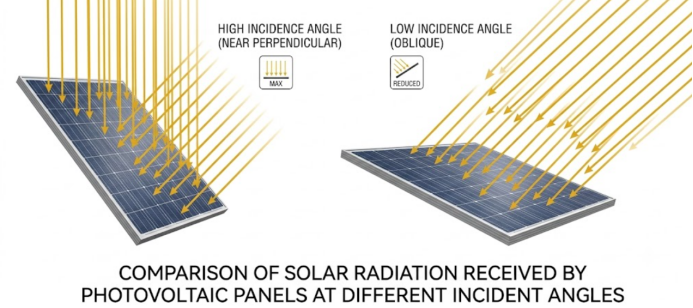
(6) Inclination Angle of Solar Panels
For inclined photovoltaic panels, different solar incident angles lead to varied normal solar radiation received per unit area. Specifically, the smaller the incident angle (the angle between sunlight and the normal direction of the panel), the greater the received normal solar radiation.
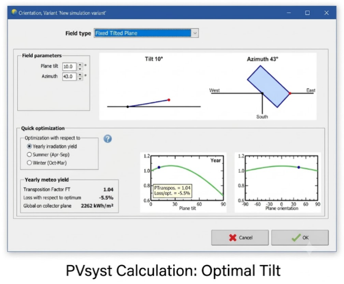
Hence, the setting of solar panel inclination angles affects power generation efficiency. The inclination angle that maximizes the total annual radiation absorption is defined as the optimal inclination angle as specified in the Code for Design of Photovoltaic Power Stations.
The calculation of the optimal tilt angle requires:
Local longitude and latitude
Multi-year average solar radiation data
PV panel azimuth angle
The analysis can be conducted via professional software such as PVsyst.
You may refer to searchable documents such as Quick Reference Table for Optimal Installation Angles and Power Generation of National On-Ground PV Power Stations and Quick Reference Table of Optimal Installation Tilt Angles, Power Generation and Annual Utilization Hours for PV Stations in Chinese Provinces and Cities to confirm the approximate optimal tilt angle.
It can be concluded from the figure that the lower the latitude of an area, the smaller the installation tilt angle.
Key Points Review
A photovoltaic system is mainly composed of PV modules, combiner boxes, distribution cabinets, inverters, transformers and other equipment.
Inverters convert direct current generated by solar power into alternating current for grid connection.
Hot spot effect refers to the phenomenon that shaded solar modules act as loads, consuming power and generating heat.
Bypass diodes can effectively mitigate the hot spot effect.
Micro-cracks parallel to main grid lines are most likely to cause solar cell failure.
Solar irradiance is in direct proportion to the output power of photovoltaic cells.
The output power of photovoltaic cells decreases as the surface temperature rises.